4. Power and Connection
4.1 External Power System Design Guide
-
Voltage range requirements
The device supports a wide-range DC 9–24V input. A 12V / 2A DC supply is recommended, and the supply must provide at least 15W of power; otherwise the device may fail to start. Under low-temperature conditions, slightly increasing the supply voltage is recommended to ensure reliable startup.
-
Power adapter notes
- When connecting the power supply directly via the aviation plug, the supply output voltage must always stay within 9–24V.
- When using extension cables, compensate for line voltage drop, but the final input voltage must not exceed the 26V upper limit.
- Odin1 does not ship with a power adapter; users must provide their own. The DC connector model on the power cable is 5521/5524.
-
Voltage surge protection warning
⚠️ Voltage transients above 26V on the power line (e.g. caused by abrupt power loss of parallel devices, electromagnetic interference, etc.) may cause permanent damage to the device. We recommend adding an over-voltage protection circuit in the power supply loop.
-
Power consumption characteristics
Operating State Power Characteristics Steady-state operation ≤ 15W (typical 11W) Cold-start peak Up to 15W (lasting ≤ 10 seconds) -
Key parameters for power supply selection
Based on the device’s peak current of 1.67A (@9V) and the 26V withstand voltage limit, the power supply must meet:
- Continuous output capability ≥ 1.8A
- Over-voltage protection threshold ≤ 26V
- Recommended power margin ≥ 25W
4.2 Connection Steps
- Connect the power supply via the aviation plug.
- Connect the USB cable to the host PC (data transfer).
- Power on and perform self-check.
4.3 Odin1 ESD Identification and Troubleshooting
4.3.1 Identification Methods
-
Observe power on startup (most intuitive and reliable)
- Connect a digital power supply, supply
12V DC, and observe the power curve. - Normal device: after power-on, the power jumps starting from about
1.6W, generally not exceeding2.5W. After roughly10seconds of fluctuation it stabilizes around1.2W, the device enters standby and the USB device can be enumerated. - Faulty device: after power-on the power is significantly higher (
3Wor even more), with small fluctuation amplitude and a final stable power well above1.2W. Disconnect the power as soon as possible.
Note: The power consumption of Odin1’s internal components is predictable under normal conditions. Abnormally high power usually indicates a short circuit; abnormally low power may indicate an open circuit or that the main chip has not been programmed.
- Connect a digital power supply, supply
-
Initial check without powering on (multimeter measurement of IO pin voltage drop)
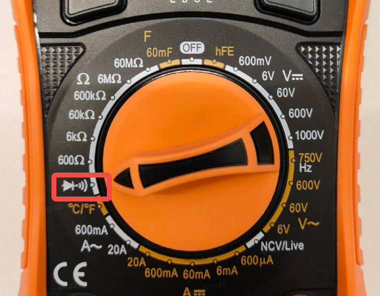
- Set the multimeter to the “diode/voltage drop” range.
- Connect the black probe to
GND, and touch the red probe to theSYNCandGPIOpins in turn, observing the readings.
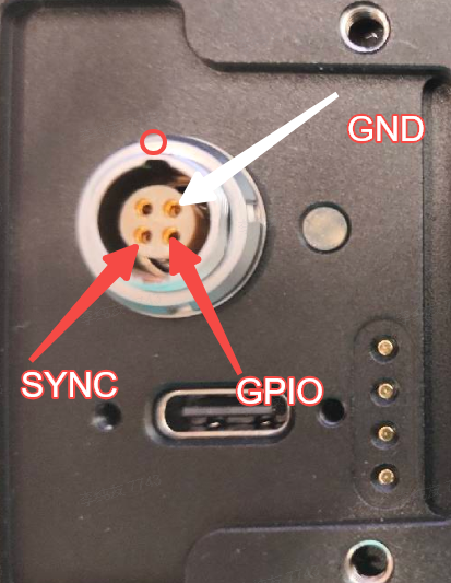
- Normal: voltage drop on the
SYNCpin is around0.9V, and on theGPIOpin around1.3V. - Abnormal: a reading below
0.65Vindicates the pin may be damaged; a complete open circuit (no voltage drop displayed) most likely means ESD on this pin has damaged the chip internally (the pin is internally blown).
Note: The voltage drop from a chip pin to ground is determined by the internal physical
PNjunction and does not require power. Normal values fluctuate within a small range; once a clear abnormality is observed, the chip can usually be considered damaged.
4.3.2 Repair Approach
Faults caused by ESD entering through the IO pins typically directly damage the internal circuitry of the SoC. Repair generally requires replacing the main control chip (or the SoC board). Once damage is confirmed, avoid further power-on to prevent additional damage to other circuits on the board.
4.3.3 Usage Recommendations
Unused IO wires on the cable harness must be fully wrapped with insulating tape or heat-shrink tubing and never left exposed, in order to reduce ESD risk at the source.