5. Data Output
5.1 Coordinate System Definition
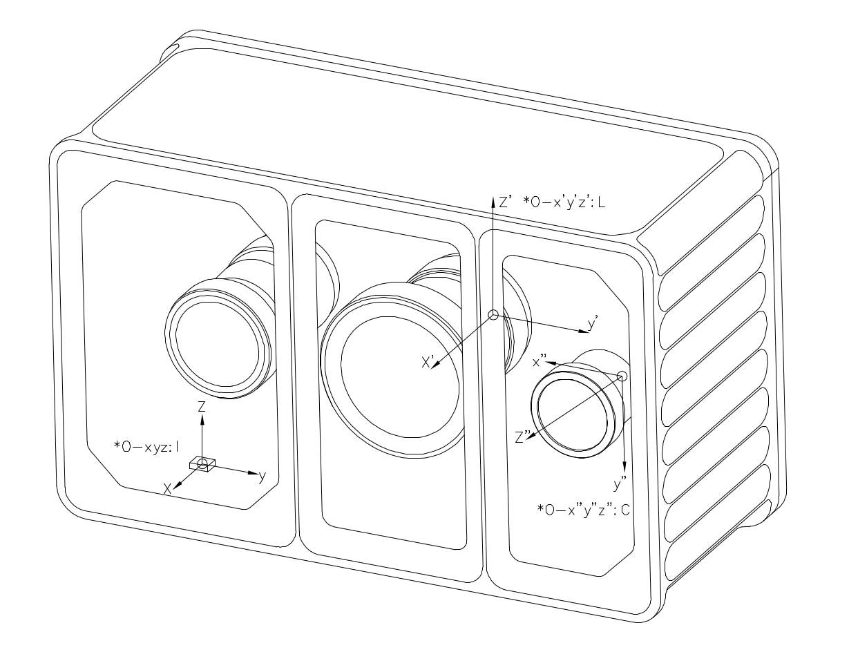
The Cartesian coordinate systems of Odin1 are defined as shown below: I is the IMU frame, L is the point-cloud (LiDAR) frame, and C is the camera frame.
5.2 Extrinsic Description
Extrinsic Notation
We use \(\mathbf{T}^{\text{A}}_{\text{B}}\) to denote a coordinate transform, with the meaning:
\[\mathbf{P}_{\text{A}} = \mathbf{T}^{\text{A}}_{\text{B}} \cdot \mathbf{P}_{\text{B}}\]where \(P_A\) and \(P_B\) are the coordinates of the same physical point expressed in frames A and B respectively.
Camera – LiDAR
The extrinsic \(\mathbf{T}^{\text{camera}}_{\text{lidar}}\) varies between individual devices. After the driver starts, retrieve the value (Tcl_0) from config/calib.yaml. See the driver for details.
IMU – LiDAR
The extrinsic \(\mathbf{T}^{\text{imu}}_{\text{lidar}}\) is fixed:
\[\mathbf{T}^{\text{imu}}_{\text{lidar}} = \begin{bmatrix} 1 & 0 & 0 & -0.02663 \\ 0 & 1 & 0 & 0.03447 \\ 0 & 0 & 1 & 0.02174 \\ 0 & 0 & 0 & 1 \end{bmatrix}\]Other
- If the Camera-to-IMU extrinsic is needed, derive it from the two values above.
5.3 Intrinsics
This section focuses on the camera intrinsics; LiDAR intrinsics are not considered.
5.3.1 Odin1 Camera Intrinsics
- How to obtain the intrinsics: connect the device and run the driver. A
calib.yamlfile will be generated in/ws/src/odin1_ros_driver/config. The values differ slightly between devices. - Example
calib.yaml:
#O1-P010100079
cam_num: 1
img_topic_0: /camera/rgb
Tcl_0: [
-0.00745, -0.99997, -0.00018, 0.03127,
-0.00938, 0.00025, -0.99996, 0.01817,
0.99993, -0.00745, -0.00938, -0.00955,
0, 0, 0, 1
]

cam_0:
  cam_model: FishPoly
  image_width: 1600  # 1920
  image_height: 1296  # 1080
  k2: 5.0379242441551616e-05
  k3: -7.4415257914767799e-03
  k4: -4.1365539417288134e-02
  k5: 5.5346546592564667e-02
  k6: -3.3479736619860797e-02
  k7: 5.9355751390599035e-03
  p1: 0.
  p2: 0.
  A11: 7.3735683773268692e+02
  A12: -4.0977897450998052e-01
  A22: 7.3729158717678535e+02
  u0: 7.9437192080462398e+02
  v0: 6.6625886729029014e+02
  isFast: 0
  numDiff: 3000
  maxIncidentAngle: 120
5.3.2 Camera Model Description
Odin1 RGB Camera Model and Intrinsics
This section describes the projection model and intrinsic parameters of the Odin1 RGB camera, for engineering reference.
1 Camera Projection Model
The Odin1 RGB camera uses an equidistant projection combined with a full-order continuous polynomial distortion model.
References:
- https://github.com/manifoldsdk/odin_ros_driver/blob/main/include/polynomial_camera.hpp
- https://github.com/gaowenliang/camera_model/blob/master/include/camera_model/camera_models/PolyFisheyeCamera.h
Note: this model is parameterized differently from OpenCV’s cv2.fisheye (Kannala–Brandt) and is not a drop-in replacement.
After undistortion, the model can be reduced to a standard pinhole model.
2 Polynomial Fisheye Model
2.1 Projection Equations
Given a 3D point in the camera frame:
\[\mathbf{P_c} = (X, Y, Z)^T\]Compute the incident radius:
\[r = \sqrt{X^2 + Y^2}\]Compute the incident angle:
\[\theta = \arccos\left(\frac{Z}{\|\mathbf{P_c}\|}\right) = \arccos\left(\frac{Z}{\sqrt{X^2 + Y^2 + Z^2}}\right)\]Polynomial radial mapping (note that the linear $\theta$ term is included):
\[\theta_d = \theta + k_2\theta^2 + k_3\theta^3 + k_4\theta^4 + k_5\theta^5 + k_6\theta^6 + k_7\theta^7\]Project to the distorted plane:
\[x_d = \frac{\theta_d}{r} \cdot X\] \[y_d = \frac{\theta_d}{r} \cdot Y\]2.2 Affine Transform
\[\begin{bmatrix} u \\ v \end{bmatrix} = \begin{bmatrix} A_{11} & A_{12} \\ 0 & A_{22} \end{bmatrix} \begin{bmatrix} x_d \\ y_d \end{bmatrix} + \begin{bmatrix} u_0 \\ v_0 \end{bmatrix}\]Parameter Description
| Parameter | Description |
|---|---|
| k2–k7 | Polynomial distortion coefficients |
| A11 | Focal length along X (horizontal scale) |
| A12 | Non-orthogonality compensation (skew) |
| A22 | Focal length along Y (vertical scale) |
| u0, v0 | Principal point coordinates |
Tangential distortion is not modeled:
\[p_1 = p_2 = 0\]2.3 Pinhole Model after Undistortion
After undistortion:
\[u = f_x \frac{X}{Z} + c_x\] \[v = f_y \frac{Y}{Z} + c_y\]Intrinsic matrix:
\[K = \begin{bmatrix} f_x & 0 & c_x \\ 0 & f_y & c_y \\ 0 & 0 & 1 \end{bmatrix}\]Distortion coefficients are zero after undistortion.
2.4 Coordinate System
The Odin1 RGB camera follows the OpenCV camera-frame convention:
- X → right
- Y → down
- Z → forward
Right-handed coordinate system.
2.5 Engineering Notes
- Undistortion does not change the extrinsics.
- For high-precision reprojection, use the polynomial fisheye model.
- For detection, SLAM, fusion and similar algorithm pipelines, use the undistorted pinhole model.
- Numerical instability can occur when $\theta \to 0$ (since $r \to 0$ leads to division by zero).
2.6 Summary
The Odin1 RGB camera model has two parts:
- Polynomial fisheye projection (raw model)
- Undistorted pinhole representation (algorithm-friendly model)
Choose the appropriate model based on your use case.
5.4 Data Description
- The raw point cloud (
odin1/cloud_raw) has the following fields:
float32 x             // X axis, in meters
float32 y             // Y axis, in meters
float32 z             // Z axis, in meters
uint8  intensity      // Reflectivity, range 0–255
uint16 confidence     // Point confidence, actual value range from 0 to around 1300 in typical scene, higher value means more reliable. Recommanded filtering threshold is 30-35, should be adjusted accordingly.
float32 offset_time   // Time offset relative to the base timestamp, unit: s