2. Hardware Description
2.1 Physical Interface
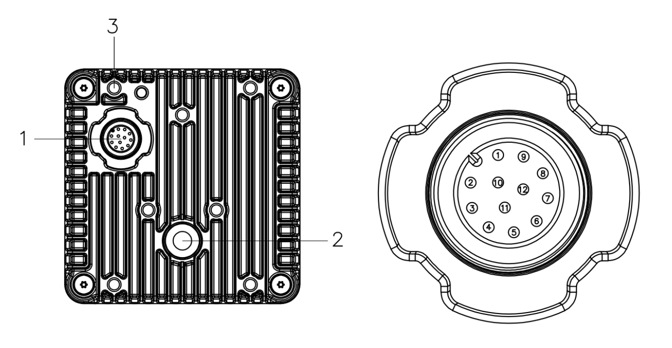
Odin1 Lite has only one aviation-plug interface. Through the included power-and-data splitter aviation cable, it simultaneously implements power supply and data transmission:
| No. | Interface Type | Cable | Function Description |
|---|---|---|---|
| 1 | Aviation plug (device side) | Power-and-data splitter aviation cable | Power + Gigabit Ethernet data transmission |
| 2 | DC jack (cable side) | 5.5×2.1 mm DC male | Connect to 12 V / 2 A adapter |
| 3 | RJ45 (cable side) | Gigabit Ethernet | Connect to PC Ethernet port or switch |
2.2 Interface Definition
Odin1 Lite uses a 12-pin aviation socket that simultaneously carries power, Gigabit Ethernet and external sync signals. The pinout is as follows:
| Pin | Signal | Attribute | Function |
|---|---|---|---|
| 1 | DC+ | Data | Gigabit Ethernet signal |
| 2 | VIN | Power | Power positive |
| 3 | DB− | Data | Gigabit Ethernet signal |
| 4 | DB+ | Data | Gigabit Ethernet signal |
| 5 | DD+ | Data | Gigabit Ethernet signal |
| 6 | DD− | Data | Gigabit Ethernet signal |
| 7 | DA+ | Data | Gigabit Ethernet signal |
| 8 | DA− | Data | Gigabit Ethernet signal |
| 9 | DC− | Data | Gigabit Ethernet signal |
| 10 | GPIO_OUT | GPIO | External sync trigger signal input |
| 11 | GND | Power | Power negative |
| 12 | FSYNC_OUT | GPIO | Sync trigger signal output |
The Gigabit Ethernet port uses four differential pairs: DA±, DB±, DC±, DD±, corresponding to the 1000BASE-T standard.
2.3 Core Components
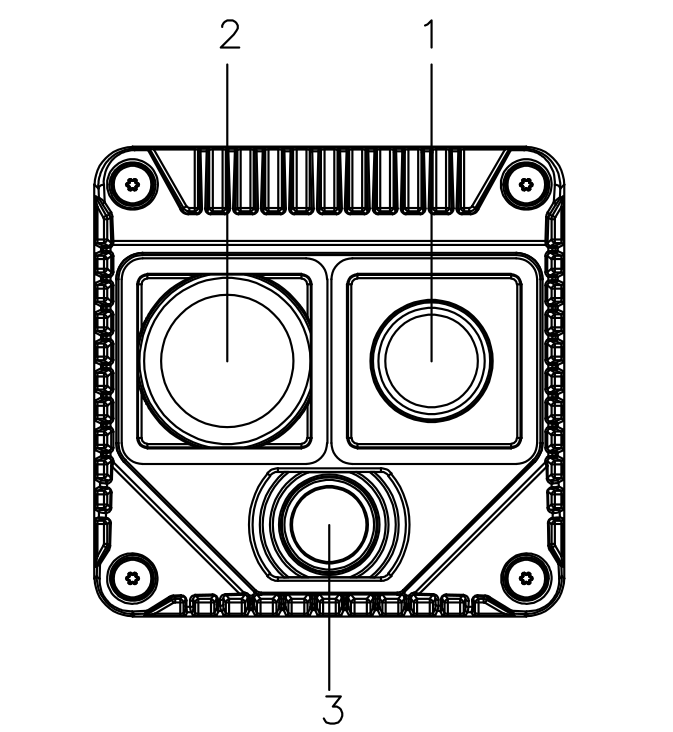
| No. | Component | Description |
|---|---|---|
| 1 | Laser transmitter (TX) | dToF TX |
| 2 | Laser receiver (RX) | dToF RX |
| 3 | RGB camera | 1280×1088 |
2.4 IMU Position Relationship
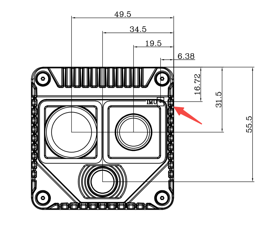
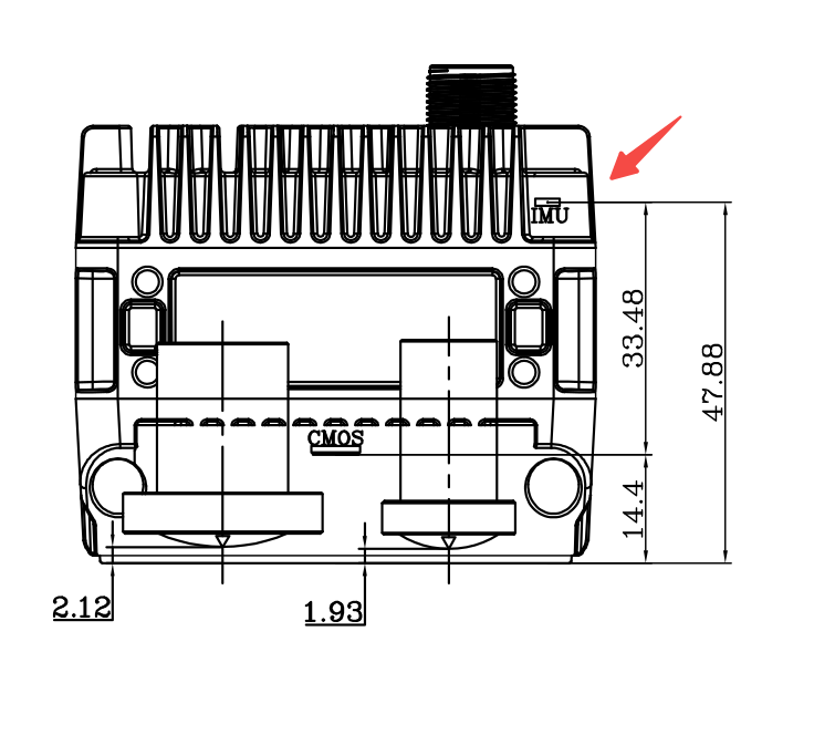
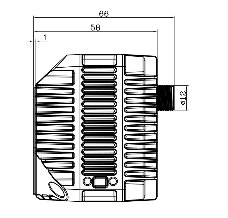
Note: The IMU and Body_base_link are at the same physical location; only the names differ. The following drawings show the IMU installation position inside the device housing and its spatial relationship with each sensor.
| Front View | Side View | Top View |
|---|---|---|
 |  |  |
| Item | Description |
|---|---|
| IMU position | The IMU is located inside the device and fastened to the main structural part. It is in the same rigid body as the LiDAR optical center and the RGB camera (CMOS). |
| Body_base_link coordinate frame | The IMU coordinate frame is the Body_base_link coordinate frame, with its origin at the geometric center of the IMU chip. |
| Relationship with housing | The IMU is fastened to the main structural part of the device. Housing changes do not affect the extrinsics between the IMU and LiDAR / camera. |
| Installation orientation | The device supports installation in any orientation; the IMU will automatically calibrate to the gravity frame. |
2.5 Network Parameters
| Item | Value | Note |
|---|---|---|
| Factory device IP | 192.168.1.251 | Modifiable |
| Communication protocol | UDP (data) + HTTPS / mTLS (file transfer) | Ports 60000–60010, 59000–59005, 8080 |
| HTTP Dashboard | http://192.168.1.251:8080 | Device status / calibration / OTA / network configuration |
2.6 CAD Models
- Download Odin1 Lite straight aviation-plug CAD model (STP)
- Download Odin1 Lite right-angle aviation-plug CAD model (STP)
← Previous Chapter:Product Overview | Next Chapter:Installation Guide →