3. Installation Guide
Before installing Odin1 Lite, please read the following precautions:
- Clean the mounting surface and window:
- Before installation, remove dust, oil and other contaminants from the mounting position and the LiDAR optical window. It is recommended to blow off dust with clean air, then gently wipe the window with a lint-free cloth (such as a lens cloth) dampened with a small amount of water until completely clean. Residual stains will affect measurement accuracy. Do not use irritating liquids for cleaning.
- ⚠️ Ensure the field of view is unobstructed:
- During installation, no obstructions are allowed in the sensor’s front field-of-view (FOV) area. Note: even transparent glass, acrylic plates, etc., installed directly in front of the sensor will significantly interfere with the laser signal and degrade performance.
- Flexible installation orientation (including optimization suggestions):
- This product supports installation in any orientation (including upside-down).
- The device will automatically adapt to the installation attitude (such as upside-down or tilted), and internal sensors will calibrate to the gravity frame.
- ⚠️ Do not apply additional load:
- The device body (especially the heat-dissipation housing and optical window) cannot bear additional weight or pressure. Please fix it only through the designed mounting interfaces (such as the bottom threaded holes).
- ⚠️ Ensure heat-dissipation space:
- Sufficient space must be left around the device for heat dissipation. Requirement: the minimum clearance between the device body and surrounding objects ≥ 10 mm, ensuring smooth air circulation and preventing overheating.
- Secure installation:
- It is strongly recommended to mount the device on a sturdy bracket, with the bottom of the sensor at least 0.2 m above any object, to avoid obstructing the field of view.
- ⚠️ Reverse polarity is strictly prohibited:
- Please read the instructions and pin definitions carefully.
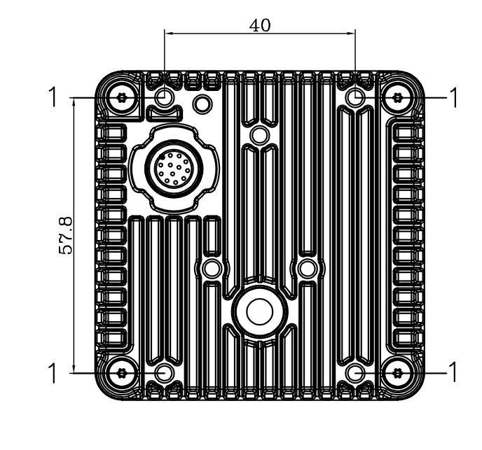
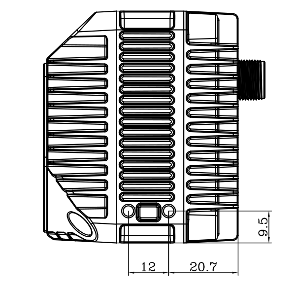
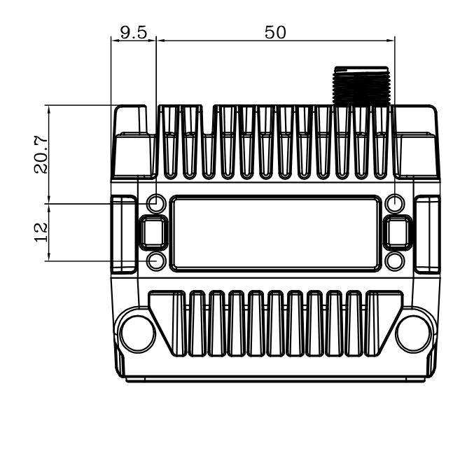
3.1 Mechanical Installation
| Back M3 mounting holes | Left/right side M3 mounting holes | Top/bottom side M3 mounting holes |
|---|---|---|
 |  |  |
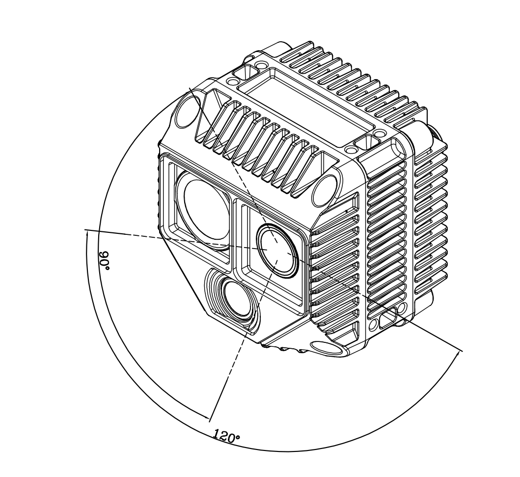
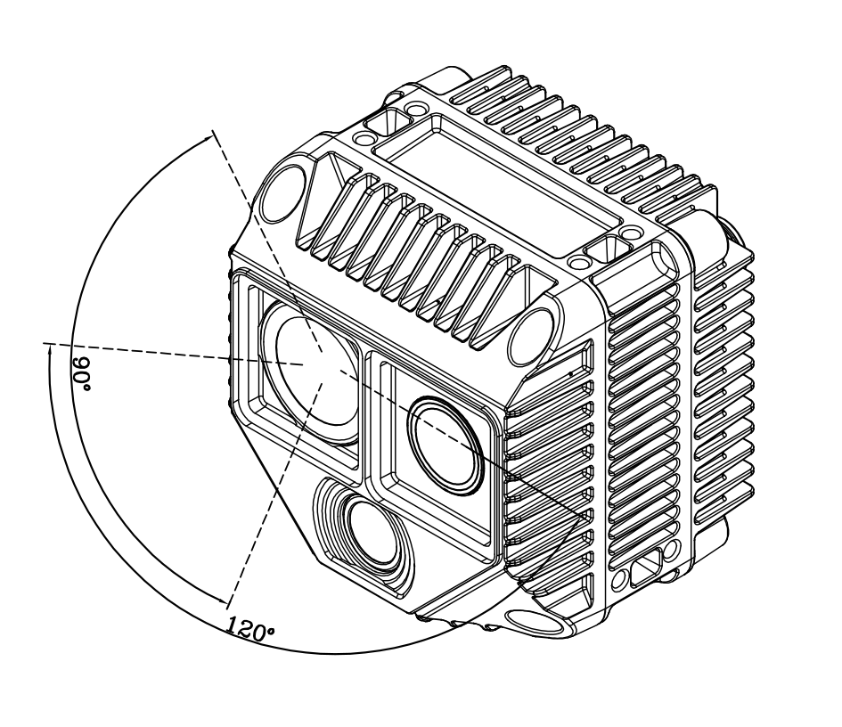
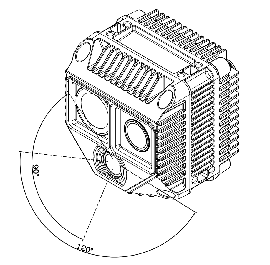
Effective field-of-view (FOV) ranges:
| TX | RX | RGB |
|---|---|---|
 |  |  |
3.2 CAD Models
← Previous Chapter:Hardware Description | Next Chapter:Power and Connection →